
Contact Details:
Festo (PTY) Ltd
18 - 26 Electron Ave
Isando
Kempton Park
Gauteng
1600
South Africa
Tel: +27 (0)8600 33786
Fax: +27 (0)11 974-2157
Send Enquiry | Company Information
Best practice for Function Integration
Product News Tuesday, May 13, 2014: Festo (PTY) Ltd
When electrical and pneumatic subsystems are separated, all the phases of building even relatively simple systems can take a lot of time. This can result in delays and dissatisfied customers. Function integration can solve this, as it offers increased functionality and reliability, reduced interfaces and saves time along the entire value chain. This improves efficiency and productivity throughout the company.
This white paper presents information on:
- Trends towards function integration in machine and system building
- Interface conflicts and requirements in day-to-day projects
- The benefits of valve terminals in eliminating interface conflicts
- Application example of function integration
- Potential reduction in the total cost of ownership (TCO) in the application example
- Key factors when selecting an integrated automation platform
The trend towards function integration
In machine building, the scale and the technical complexity of automated systems is constantly increasing. Electrical and pneumatic drive and control technology, decentralised intelligence and special safety and diagnostic functions are mixed and combined with an ever higher level of customisation.
To solve this properly would require a degree of harmonisation that takes up even more time. The additional stress this can cause often unnecessarily damages relationships between colleagues. That is why integrated solutions that are also more efficient are the answer. Small changes at the start of a project are often enough to simplify the processes for all other departments.
Specialised function integration and the knowledge needed to implement it are becoming more and more important. For the perfect combination of all the different technologies, both multi-disciplinary approaches and flexibility are a must. These two factors are the key to increasing efficiency and productivity – and milestones on the road to Industry 4.0.
Good project processes avoid interface conflicts and optimise the processes
The project process for building a machine or system involves a wide range of departments, from design, purchasing, warehousing and assembly to commissioning. As global competition intensifies, the hours allocated to these tasks in the project budget are constantly reduced; this goes for designers, assembly technicians and commissioners alike. In addition, increases in general costs sometimes need to be taken into account too, as the complexity of purchasing and accounting processes, or warehousing increases. These hidden costs drive up the prices of the machines and systems even further, and make acquisition more difficult.
New laws such as the EC Machinery Directive MRL 2006/42/EC and the associated standard EN ISO 13849-1 also necessitate new, multi-disciplinary approaches, as proof is needed that all aspects of an emergency situation have been taken into account (e.g. safely preventing a movement using both electric and pneumatic parts, diagnostics, programming).
Short times to market and increased flexibility and customisation present extra challenges in addition to those of upcoming trends, such as intelligent interpretation of information on surroundings, or energy efficiency.
These requirements and trends can only be optimally implemented when all the departments involved understand the entire system and adopt a holistic optimisation approach. Valve terminals with intelligent, integrated, electrical and pneumatic functions and safety modules help when thinking outside the box, instead of focusing on subsystems or individual components.
In keeping with the vision of a highly flexible, self-managing, productive Industry 4.01, (or Integrated Industries) much more intelligent, interconnected processes and models with standardised networks are needed. Companies that are already basing their models on intelligent, modular platforms have an advantage, as they are already keeping all their options open for tomorrow and beyond. In addition, machine and plant engineers need to overcome their departmentalised approach, e.g. with product and solution packages that provide all-in-one solutions.
Valve terminals with function integration and decentralised intelligence support this multi-disciplinary approach, as they create synergies between staff and between the various technologies, and also provide options for Industry 4.0. The following section and detailed example explain how this works.
Click here for more information on the topic of Industry 4.0
The table below lists typical problems and conflicts in the everyday project work of machine and system builders, and thus paves the way for long-term process improvement.
Commissioning and diagnostics
- Tedious system and component configuration due to use of different parameterisation software programs or missing software modules
- Unnecessary, time-consuming tasks for many stand-alone components,
e.g. setting up multiple IO modules with their own bus systems
- Diagnostics options become more difficult with non-harmonised components
|
Process step
|
Typical problems and conflicts
|
|
Mechanical + electrical design
|
- Lack of communication between mechanical and electrical engineers leads to weak/neglected function integration
- Task-by-task approach leads to separate component orders. Potential synergy effects in ordering and the subsequent supply chain remain unexploited
- Configuration, download and integration of many individual components into the CAD system takes a lot of time
- Different electrical configuration and parameterisation software for each individual component multiplies the required amount of supervision and engineering work
- Over-sized solutions due to accumulated performance and safety reserves
|
|
Legal safety requirements
|
- Difficulties in calculating the performance level due to components from several manufacturers with different levels of detail in documentation
- Large amount of coordination required between departments and different suppliers in order to achieve the legally required safety levels
|
|
Procurement
|
- Separate order processes for many individual parts. This results in additional work, e.g. certifying and entering details for new suppliers
- Higher costs due to minimum order prices with each supplier
- Little influence on discount negotiations as many individual parts are purchased from several manufacturers
|
|
Incoming goods
|
- Significantly greater workload as all logistics processes need to be carried out separately for each component: checking goods, unpacking, order allocation, booking into system, storage
|
|
Assembly
|
- On-the-spot improvisation required if anything has been missed off the plan, e.g. if assembly boreholes have not been made
- Increased workload when assembling components and performing wiring, due to lack of function integration
- Waiting and inactive times due to missing partial component deliveries
- Greater labelling workload due to lack of function integration, as more compressed air and electrical cables need to be installed
|
|
Table 1: Typical problems and conflicts in the project process for machine and system builders
The benefits of valve terminals
Valve terminals stand for a lighter workload and lower automation costs. Their mechanical, pneumatic and electric features are highly adaptive. The individual combination options for the different functions on a terminal mean that the valve terminal can be precisely configured to suit the application. These holistic solutions reduce the efforts required during procurement, receiving and checking of goods to a minimum. Assembly, configuration and commissioning are made easier. Maintenance and service become less time-consuming. Error rates can be reduced using pre-assembled and inspected units.
And valve terminals verifiably reduce installation times by up to 60%.
Best practice – Application example of a valve terminal with function integration
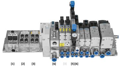
The valve terminal shown below is used in part of an automation system for manufacturing fuel cells. It controls and regulates various clamping and transfer cylinders, the knuckle-joint press, the suction unit for the punch grid and two compressed air motors. The design engineer worked with an electrical engineer to define the necessary functions for the valve terminal, and integrated all the requirements for safety, for the pneumatic and the electrical system with the help of his technical adviser:
The following functions were previously implemented separately, but have now all been integrated into the valve terminal:
- One fieldbus interface [1]
Bus systems offer advantages as they require less time for wiring, commissioning and troubleshooting. The AIDA* push-pull interface for fibre-optic cables supports this, and provides greater safety during data transmission as static charges and discharges cannot affect the fibre-optic cable.
*(Automation of German Domestic Automobile Manufacturers)
- One sensor input module [2]
Since the signals of the nearby proximity sensors are processed directly, there is no need to order or wire a separate sensor/actuator box. Troubleshooting is made easier by this module's diagnostics options. This simplifies the ordering process and streamlines all the subsequent processes.
- One electronic safety component [3]
When changing materials or the punch blade, or starting the unit up again after these procedures, it is sometimes necessary to open up the machine. This is subject to Performance Level e (PLe). This performance level is attained through the integration and combination of a PROFIsafe shut-off module with a press safety control unit.
The advantage for design and electrical engineers is the simplicity of defining the performance level, as all the individual components come from a single source and are all checked and certified. Moreover, a second PROFIsafe output can be used to control a soft-start/quick exhaust valve. This further increases the safety level of the remaining valve functions.
- One soft-start/quick exhaust valve [4]
In order to minimise the risk of damage or accidents caused by an unspecified stop (emergency stop), it is important for the cylinder to move to its home position slowly and in a controlled manner. This is achieved using a soft-start/quick exhaust valve with maximum venting capacity to ensure that the machine stops as quickly as possible in case of an emergency.
- One 5/2-way valve with pressure regulator, pressure gauge and exhaust air flow control [5]
This clamps and tensions the membrane during cutting. Six individual components are rolled into just one for the design engineer to install. This also saves making additional assembly bore holes on the machine (and in CAD).
- 2x 3/2-way valves with pressure shut-off plate [6]
These valves are required to switch two compressed air motors that move the punch grid forwards and keep it clamped in place. Since the compressed air motors are switched on and off very often, a high level of wear is to be expected, causing the valves to fail. With the pressure shut-off plate it is no longer necessary to depressurise the whole system when changing the valve. The advantage of this is that the clamping cylinders are kept in position, and the dancer tension upstream of the punch is maintained during the valve change. This avoids unnecessary consumption of expensive membrane materials when stopping and restarting the machine.
The punching procedure generates fine particles that contaminate the system and impair its reliability. As such, it is best to choose a valve terminal like the metal version of the VTSA with electrical terminal CPX. This fulfils the requirements of protection class IP65/67, and has extra dust protection.
Total cost of ownership calculation
A saving of 825 minutes
The high level of function integration in the application example above saves almost 14 hours over the course of the entire project. As the valve terminal is processed as one part with only one part number, it can be configured quickly using a standardised method. This helps to reduce hidden costs.
The design engineer can configure all the components in the valve terminal module quickly and easily, assisted, as and when needed, by the manufacturer's technical support team. He can download the generated model and the corresponding PDF parts list in just a few minutes, and integrate them into the module with a few quick CAD steps. The total time required for this solution is approx. 30 minutes. Without a solution approach that integrates functions from the three fields of pneumatics, electrics and safety, it would take much longer as each component would have to be processed individually. It would mean individually processing 28 components and integrating them into the CAD system: press safety unit, soft-start/quick exhaust valve, 15 different individual components for functional display and 13 additional components such as push-in fittings, mounting brackets, silencers and valve connectors. Performing the myriad of individual steps – searching and configuring, downloading, creating a port pattern, integrating the CAD model into the CAD module, creating and releasing the CAD model in the PLM system and attaching the necessary documentation for each component – vastly increases the design engineer's workload. The potential saving for these steps is over 460 minutes. Another 70 minutes can be saved using an automated pneumatic circuit diagram generator such as FluidDraw, and by the simpler electrical circuit diagram generation via the fieldbus.
The total engineering time can be reduced by 530 minutes.
TCO time savings: 825 minutes = 13,75 h
Purchasing and warehousing departments also save a lot of time thanks to the material numbers being reduced from 28 to one. This is because process steps such as ordering, accounting, receiving and checking goods, system bookings and putting goods in storage only need to be performed once for the valve solution. With our solution, this takes only about 10 minutes. For the individual component solution, on the other hand, much more time is needed – approx. 180 minutes. This means a saving of 170 minutes.
The startup engineer can also reduce the assembly time for the mechanical and electrical aspects of a valve terminal solution compared to that for individual assembly. A total of 90 minutes can be saved on assembly compared to an individual component solution. Due to the variety of components that need electrical and pneumatic connections, the individual wiring also requires much more time, i.e. approx. 100 minutes.
This means that the startup engineer can save a total of 190 minutes.
The commissioning engineer also saves 10 minutes of working time thanks to faster error diagnostics, based on an error rate of 3% and a higher diagnostics workload of 5 minutes per error.
The TCO time calculation shows that the total time benefit for the company on this project is over 825 minutes.
|
Function/process step
|
Valve terminal with function integration
|
Individual component solution
|
Time saved
|
|
[Minutes]
|
[Minutes]
|
[Minutes]
|
|
Engineering [CAD etc.]
|
60
|
530
|
470
|
|
Purchasing and logistics
|
10
|
180
|
170
|
|
Assembly and commissioning
|
15
|
190
|
175
|
|
Troubleshooting
|
-
|
10
|
10
|
|
Total
|
85
|
910
|
825 min
? approx. 14 h
|
Table 2: comparison of time required with and without function integration
A worthwhile principle: the valve terminal
In practice, the time saved may differ, as it is dependent on a number of individual factors – from the technicians' experience and speed to the complexity of the system. In spite of this, the use of valve terminals is worthwhile in almost every case, as the time savings mentioned in the above points greatly outweigh the extra cost of the valve terminals. Just as important is the more reliable operation guaranteed by the reduced number of errors during operation, maintenance, assembly and repair work – a result of a much clearer and simpler structure.
Guide: key factors for the best solution
The table below shows key factors that should be taken into account when selecting an integrated automation platform. Fully integrated automation platforms offer advantages for engineers who wish to combine the disciplines of pneumatics and electrical engineering. For example, electric cam disks can also be shown on valve terminals. Integrated motion control even makes it possible to operate several Cartesian handling systems. Even low-cost servopneumatic solutions are easy to implement. Control blocks can be used to apply concepts with decentralised intelligence. Time spent programming can also be easily reduced, as it is no longer necessary, for example, to convert analogue values for proportional valves and pressure sensors.
The integration of universal networks also opens up a wide range of options, especially with regard to additional IT service and web-based monitoring and diagnostic functions.
|
Check list for selecting a valve terminal
|
|
Terminal platform architecture
|
Are pneumatic and electric control modules supported? Does the valve terminal support different valve sizes?
|
|
Range of pneumatic modules
|
Are all the common standard modules – pressure regulators, pressure gauges, flow control valves etc. – available? What other modules are there, e.g. pressure shut-off plate?
|
|
Communication interfaces
|
Are all conventional, industry-standard fieldbuses and Ethernet nodes available? Is it possible to integrate other decentralised modules?
|
|
Energy/air supply
|
Can different compressed air and vacuum zones be set up? What about independent electronic voltage zones?
|
|
Range of electrical modules
|
Is there a sufficient range of available analogue and digital I/O module variants?
|
|
Electric drives
|
Does the platform allow use of control modules, e.g. for servo-pneumatic or electric movements?
|
|
Proportional technology
|
Is it possible to integrate proportional valves?
|
|
Safety
|
Are the safety components certified and can they be integrated in accordance with the legal regulations?
|
|
Diagnostics
|
How extensive are the diagnostics options?
|
|
Environmental protection
|
Which IP classes does the platform conform to?
|
|
Software
|
How much does the required configuration software cost, e.g. for the integrated control system? Or is it available as open-source software?
|
|
Individual control unit
|
Is it possible to integrate decentralised, intelligent control systems?
|
|
Energy efficiency
|
What options are available for increasing energy efficiency?
|
Table 3: key factors in selecting the right automation platform
Making the most of automation potential
Now and in the future, the market needs reliable pneumatic and electrical products for all forms of industrial communication. All-in-one solutions and universal system concepts together with expert consultation are the central success factors.
Valve terminals with a high level of electrical and pneumatic function integration can help machine and system builders save valuable time during design, procurement, assembly and commissioning. Function integration in automation platforms significantly reduces the number of interfaces. What was once a group of simple valves is now a decentralised control system that can automate the whole machine – including motion control! Saving time means saving money. Trend-setters in every sector have already recognised this potential and begun to implement it with an eye on Industry 4.0.
Automation platforms such as valve terminals with CPX can be used as universal standards in process and factory automation applications. Due to their wide range of modular capabilities and variants, they can be designed and customised to a high level of individuality.
Publisher/author:
Festo AG & Co. KG
Philipp Wahl
Marketing Concepts
E-mail: pwhl@de.festo.com
Your local contact:
Festo (Pty) Ltd
Tracey Swart
Marketing Coordinator
Email: tracey.swart@za.festo.com
Tel: 08600 FESTO (33786)
Reference: [1] Prof. Dr. Dr. h.c. mult. Wolfgang Wahlster in “trends in automation”, 2/2012