
Contact Details:
Metallurgical Technologies, Inc.
160 Bevan Drive
Mooresville
NC
28115
United States of America
Tel: +1 704 663.5108
Fax: +1 704 662.0898
Send Enquiry | Company Information
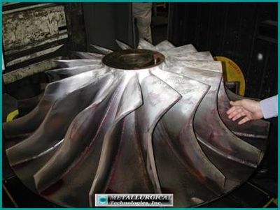
Analysis Of A Cracked Impeller Blade
Service News Thursday, May 23, 2013: Metallurgical Technologies, Inc.
Two blade samples of a cracked ******************* centrifugal blower impeller blade was submitted for metallurgical analysis of the cracks. The cracks in the submitted blade samples were found to have initiated at corrosion pits on the leading edge of the blades. Initial propagation was by stress corrosion cracking (SCC). Further propagation occurred by corrosion assisted fatigue throughout the remaining crack lengths. The maximum depth of SCC was found to be about 0.370 inch from the leading edge surface. The initiation site of the main crack was found to be slightly beyond the toe of an assembly weld. Minor secondary cracks were found in the same region.
Both blade samples submitted exhibited corrosion pitting mainly concentrated along their leading edges. None to very little of a protective coating remained at the location of cracking.
Energy dispersive x-ray spectrographic (EDS) analysis taken along the attack front of a longitudinal metallurgical cross-section taken through a corrosion pit indicated significant amounts of lead, sulfur and a trace of chlorine. Chlorides and sulfides are known to cause SCC in high strength PH stainless steels. High temperature water may also cause SCC in 17-4 PH stainless steel. Lead can cause cracking by solid (or liquid) metal-induced embrittlement, although none was observed in the submitted pieces.
The blade base metal and remnant weld metal were determined to be 17-4 PH by optical emission spectroscopy. The microstructure of the blades was tempered martensite, typical of 17-4 PH in the hardened condition. The microstructure exhibited some carbide precipitation at the grain boundaries; however, SCC cracking was found to be mainly transgranular.
Cracking was limited to the area where the coating had been removed during service. The coating appeared to protect the rest of the impeller, even where stresses were reported to be higher by finite element analysis.
The hardness of the impeller was 32 HRC, which was within the reported specification of 28 to 33 HRC.
Two 17-4 PH stainless steel impeller blade specimens were submitted for metallurgical analysis. The specimens were pieces of impeller blades that exhibited crack-like indications on, at, or near the toe of an assembly weld (blade-to-hub weld) along the leading edge of the blade. The impeller was previously found to have crack-like indications during in-service magnetic particle testing (MT) inspection in November 2008. During this inspection, it was reported that a protective coating appeared to be intact and the decision was made to leave the impeller in service until a shut down in April 2009. Additional MT testing in April resulted in an increase in the number and lengths of crack-like indications observed. It was therefore decided to remove the impeller from service for further detailed examinations.
The subject impeller was examined at the ********************** *************** **************. Figures 1 through 3represent photographs taken during the on-site inspection. These photographs show the locations for extraction and analysis of the cracked sections from first and second impeller blades.
First Blade
Visual Examination
A triangular piece of the first centrifugal blower impeller blade was submitted for metallurgical analysis of the cause of cracking. The piece had been extracted from the rest of the blade, as referenced in Figure 2. It contained an exposed surface of a crack that extended slightly beyond the assembly weld from the leading edge. Top views of the submitted piece are shown in Figures 4 and 5. A crack which encompassed the leading edge and extended down one side (pressure side) of the blade sample was observed. Corrosion pitting was noted along the leading edge and along the crack path in the blade edge, the suspected crack initiation area.
The blade sample was back-cut using an abrasive saw to facilitate opening of the crack. The opened crack surface on the submitted sample was examined with a stereomicroscope and a scanning electron microscope (SEM). The fracture surface was thoroughly cleaned using Alconox, a mild alkaline detergent, prior to examination. The mating opened crack faces are presented in Figure 6.
The crack faces show a shallow zone of heavily oxidized surface at the edge of the blade. The oxide could not be removed despite cleaning attempts, indicating it had been open to this depth for some extended time. Below the heavily oxidized region, fatigue arrest marks were observed.
Previous MT and dye penetrant examinations had contaminated the exposed crack surfaces. Therefore, the heavy oxide on the crack faces were not analyzed (subsurface deposits were subsequently ground into for analysis of corrosion deposits and are presented in a later section of this report).
Scanning Electron Microscopy (SEM)
SEM photos of the primary crack origin area are shown in Figures 7 and 8. A corrosion pit was observed within the suspected crack initiation area. Examination of the fracture surface at higher magnification revealed a heavily oxidized and corroded surface which obscured fracture surface details. An attempt was made to use a more aggressive cleaner to remove the oxide/corrosion layer, however this attempt was unsuccessful.
Back-scattered SEM imagery was used in an attempt to resolve fracture features more clearly, due to its sensitivity to topographical and compositional variations. A BSE/SEM montage fractograph is provided in Figure 9. The dark regions at the origin area and extending down the blade sides were the locations of heavy oxidation and was subsequently approximately matched to the depth of stress corrosion cracking (SCC), subsequently identified during cross-sectional metallographic analysis.
The back-scattered image revealed a fracture surface which contained numerous fatigue progression marks extending from the oxidized SCC region. The fatigue progression marks are more clearly resolved in the increased magnification BSE/SEM image provided in Figure 10.
A high magnification SEM image of the fracture surface within the fatigue progression area is provided in Figure 11. Although obscured by oxidation and corrosion, the observed fracture features appeared to be transgranular within this region, typical of fatigue progression.
Second Blade
Visual Examination
A triangular piece of the second centrifugal blower impeller blade was also submitted for metallurgical analysis of the cause of blade cracking. The piece had been cut from the rest of the blade, as referenced in Figure 3. It contained an exposed surface of a crack at or near the assembly weld along the leading edge.
Top views of the submitted piece are shown in Figures 12 and 13. A crack which encompassed the leading edge and extended down the sides of the sample blade was observed. Corrosive pitting was noted along the leading edge and along the crack within the suspected initiation area. The protective coating had mostly been removed in this area.
Scanning Electron Microscopy (SEM)
The cracked surface on the second submitted blade sample was examined with a scanning electron microscope (SEM). The blade surface was thoroughly cleaned using Alconox, a mild alkaline detergent, prior to examination. SEM photographs of the primary crack within a pit at the suspect crack origin are shown in Figures 14 and 15. High magnification examination within a corrosion pit revealed preferential attack along features in the microstructure (martensitic carbide palettes and ferrite), likely through a combination of erosion and corrosion (Figure 16).
Metallography
The second impeller blade was cross-sectioned perpendicular to the main crack, parallel to the blade edge axis, and normal to the blade edge surface, through the approximate area of crack initiation, as shown in Figure 13. This section was prepared for metallographic examination per ASTM E3 and E407.
Figures 17 through 19 are unetched photomicrographs of the longitudinal cross-section showing the main crack. The crack path exhibited branching close to the outer surface, which is characteristic of SCC or corrosion assisted fatigue. The crack progressed until transitioning, at approximate mid-crack length, from branched cracking to a straight crack path, more characteristic of fatigue propagation. The depth of the SCC region was measured to be approximately 0.370-inch. The crack continued to progress in a straight fracture path (characteristic of fatigue) to the crack tip.
A corrosion pit adjacent to the main blade crack is shown in Figure 20. This view shows the initial stages of cracking at the bottom of the pit. Branching of the crack was observed, typical of SCC.
Photomicrographs of the main crack after etching are provided in Figures 21 through 26. These images illustrate the branching crack mechanism in the initial phase of crack propagation. A faint outline of the weld deposit was observed in close proximity to the main crack. Microstructure dependant corrosive attack was also observed along the crack path, which had been observed previously during SEM examination of a corrosion pit at the blade surface.
The etched image provided in Figure 25 shows the branching crack propagation at the upper-mid-crack length, which exhibited mainly transgranular crack progression. Some branching of the crack was still observed at the crack tip which indicated the fatigue progression was likely assisted by corrosion.
Only two fine specks of coating remnants were found along the blade surface in the metallographic cross-section as shown in Figure 27. The coating remnant measured slightly less than 0.002-in. thick.
The microstructure of the blade was a tempered lath martensite, typical of 17-4PH in the hardened condition, as shown in Figure 28. Some carbide precipitates were observed along the grain boundaries indicating some sensitization had occurred. This was due to the reported air cooling after solution treating and double aging at 1150F which is in the range of carbide precipitation expected for this alloy. In some cases, grain boundary carbide precipitation can be detrimental to corrosion resistance. However, since neither pitting corrosion or cracking were intergranular in nature, it did not appear to have an effect on cracking of the impeller.
EDS Analysis
The contents of a corrosion pit deposit, which was adjacent to the main crack, was subjected to EDS analysis to investigate for the corrosive or embrittling components. Figure 29 is a BSE/SEM mage of the longitudinal cross-section through the second impeller blade at a corrosion pit. The location of EDS analysis of the corrosion product at the attack front (at the pit bottom) is referenced in this image. The EDS spectrum collected is shown in Figure 30.
Significant amounts of sulfur and a trace of chlorine were detected. This supported that the cause of the branched cracking was due to sulfide and/or chloride induced SCC. Increased chromium, oxygen and carbon were also noted. This can indicate carburization or/and likely preferential oxidation of the chromium which is typical of corrosion in stainless steels. High temperature water, also, cannot be ruled out as the SCC species.
Hardness Test
A transverse cross-section of one of the submitted blade pieces was Rockwell hardness tested per ASTM E18. The average of four tests made was 31.8 Rockwell C. This was typical of 17-4PH which has been solution treated and double aged at 1150F. It also conforms to the reported hardness specification of 27-33 HRC.
Additionally, microhardness testing was performed in fine increments across the weld and into the base metal of the cross-section in accordance with ASTM E384. Results were converted from Knoop 500-gram load to approximate Rockwell C (HRC) using ASTM E140. Results of the hardness testing across the weldment are provided in Figure 31. The weld, heat affected zone and base metal are all of uniform hardness.
Additional Analysis of Crack Tip
The far tip region of the crack portion opened in Figure 6 was subsequently opened to analyze the deposits on the newly exposed crack tip as far away from the surface as possible. The crack tip region was below the “fatigue progression zone” labeled in Figure 6. This was done in an attempt to get as far away as possible from possible contamination from the MT and PT solutions residues that may have seeped into the crack.
EDS analysis of the newly exposed opened crack surface in the tip region is presented in Figure 32. Sulfur and chlorine were detected. It is recommended that the fluids used in the MT and PT inspections be analyzed for their possible sulfur and chlorine content to ensure that the analysis does not contain their residues and give a false reading.
The chemical composition of the impeller base metal and the remnant weld metal were analyzed with an optical emission spectrometer per ASTM E1086 guidelines. The blade metal and remnant weld metal met the chemical composition requirements for 17-4 PH stainless steel (UNS No. S17400). The results of the composition analysis are shown in Table 1 below:
TABLE 1
Blade Base Metal Composition Analysis Results
(w%)
Element
Blade
Assembly Weld
UNS No. S17400
Carbon
0.04
0.04
0.07 max
Manganese
0.54
0.49
1.00 max
Phosphorus
0.027
0.011
0.040 max
Sulfur
0.002
<.001
0.030 max
Silicon
0.42
0.44
1.00 max
Nickel
4.55
4.50
3.00-5.00
Chromium
16.51
16.16
15.50-17.50
Copper
3.45
3.43
3.00-5.00
Niobium (+Ta)
0.28
0.30
0.15-0.45
- Cracking of the subject impeller blades initiated at fine corrosion pits along the leading edge of the blade at or near the toe of the assembly weld. Initial propagation was by stress corrosion cracking (SCC) and the cracks further propagated by corrosion assisted fatigue. Shallow branching stress corrosion cracks at the bottom of corrosion pits were observed within the origin area adjacent to the main crack. The depth of SCC was about 0.370 inches in the second blade. SCC propagation of the main crack continued in a branching manner until transitioning at approximate mid-fracture to a straight transgranular fracture path, characteristic of fatigue. While the remainder of the fracture path was typically straight, some minor branching was noted even at the crack tip. This indicated a component of corrosion assisted fatigue was present.
- Potential species contributing to corrosion and SCC are sulfides, sulfates, chlorides, or high temperature water.
- The microstructure of the blade piece was tempered martensite, typical of 17-4PH in the solution treated and aged condition. Some grain boundary carbide precipitates were observed which indicated some sensitization of the material had occurred. However, this did not appear to contribute to impeller cracking.
- Energy dispersive x-ray spectroscopic (EDS) analysis of the attack front of an observed corrosion pit revealed the presence of significant amounts of sulfur and a trace of chlorine, some compounds of which are known to cause SCC in 17-4 PH stainless steel.
- The blade and remnant weld material were determined to be 17-4PH stainless steel by optical emission spectrometry.
- The average hardness of the blade material was determined to be 31.8 HRC which was typical of 17-4PH in the solution treated and 1150F double aged condition.
- The microhardness traverse taken across the assembly weld, heat affected zone, and into the base material indicated uniform hardness and did not indicate any embrittlement or over-softening of the impeller blade material.
- Cracking was limited to the area along the impeller blade leading edge where the protective coating had been removed during service.
- Comparing to the previously installed impeller which exhibited cracking throughout multiple locations, the protective coating appeared to prevent cracking where it remained intact.